Add this to nginx.conf (make sure to change IPs to match your two pihole pi)
stream {

upstream dns_servers {

server 192.168.1.136:53 fail_timeout=60s;

server 192.168.1.152:53 fail_timeout=60s;

}

server {

listen 53  udp;

listen 53; #tcp

proxy_pass dns_servers;

error_log  /var/log/nginx/dns.log info;

proxy_responses 1;

proxy_timeout   1s;

}

}
This post talks about rack mounting a RTL-SDR reciever attached to a raspberry pi into a 1U case. The donor case used was a used kramer broadcast 1110 balanced audio distributor, but any 1U case should work.
Parts Needed:
1U Case
5V 3A power supply (Mean Well RS-15-5)
Raspberry Pi
Class 10 SD Card
rtl-sdr receiver with antenna
Short 6″ ethernet patch cable
panel mount ethernet jack (“search ebay for “ip68 ethernet”)
Find the SD card on the computer and add an empty file to it with the file name “ssh” (no extension). This will enable ssh on boot
Power up the raspberry pi with ethernet connected.
Find the address of the pi by port scanning with a tool like Nmap or looking at your routers DHCP allocation table.
Use a tool like Putty to ssh into the pi on port 23. User name “pi” Password: “raspberry”
Its a good idea to change the password when you log in using the passwd utility
Optional: since this is going to be a headless install it would be a good idea to lower the video memory using raspi-config.
Now run these commands to get Osmocom rtl-sdr up and running on the pi:
sudo apt-get update

sudo apt-get install git cmake build-essential libusb-1.0 libpulse-dev libx11-dev

git clone git://git.osmocom.org/rtl-sdr.git

cd rtl-sdr

mkdir build

cd build

cmake ../ -DINSTALL_UDEV_RULES=ON

make

sudo make install

sudo ldconfig
Now you should be able to run rtl_tcp -a IpAddressOfPiGoesHere If an error pop up like Failed to open rtlsdr device #0. run sudo rmmod dvb_usb_rtl28xxu rtl2832 This will prevent the pi from loading the stock drivers for the dongle.
The goal of this is to create some network attached GPIO with some of the HP Jetdirects in my junk box. Here are some of the web sites used to figure this out:
As far as hardware the project was started with a Jetdirect 300x this was replaced with a 170x. The 300x has 10/100 base t which is why it was initially chosen. This was later replaced with the 170x which is only 10 base t. If you are looking to buy hardware, shoot for the 170x. The 300x, at least the one tested, does not appear to be as stable as the 170x.
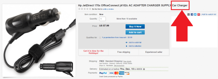
The Jetdirects did not come with a power supply. The power connector was a somewhat weird diameter. Sourcing the power supply on Ebay proved more time consuming and expensive than desired. The search did lead to this listing which is hilarious. Just picture a person driving with a wired network and a printer in their car. No one probably ever buys this…
The easiest solution for this was to pop open the case and solder some wires to the power connectors. That was also a problem since HP was nice enough to use some super tiny Torx security bits. A quick trip to the hardware store and the screws were no match for my new set of security screwdriver bits.
These wires were then attached to a surplus 12v wall wart.
The original PCB did not have the connection on the DB25 connector between pins 1, 10, 13 and 15. This was added later on with some red 30 awg wire wrap wire.
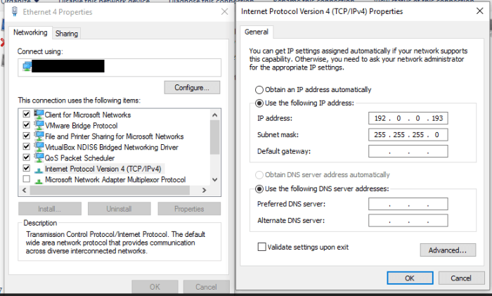
The first problem that was encountered was finding the Jetdirect’s IP address. Usually this would be a simple task. All that would be required is holding down a button on startup and the jet direct would print out a configuration page that lists its IP address. This would be easy other than the fact that I no longer own a printer with a parallel port interface. The device is supposed to have a default IP of 192.0.0.192 so that was tried first. After some reading it appears that if the device is power cycled while holding the
“test”button and releasing after 5 seconds it will go into reset and have factory defaults. After this was accomplished it was possible to ping, telnet and connect to the device using a web browser.
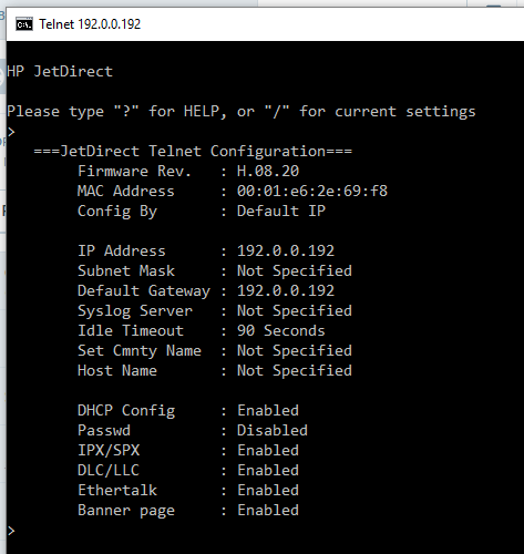
The telnet interface looked somewhat primitive so I opted for the web interface. The web interface failed to load in chrome so IE was tried. IE gave this lovely error:
After updating Java and adding the IP to the trusted sites in the java control panel, the web interface still did not work.
After some reading this is due to stricter security in the newer versions of Java. The work around for this was to use the telnet interface.
The jet direct’s default IP address of 192.0.0.192 was not convenient so it was changed to be in the 192.168.1.xxx range. This was done by issuing the command ip: 192.168.1.170 (or whatever IP you want) hitting enter then typing quit. After that wait one minute and power cycle the Jetdirect. The Jetdirect should now show up hopefully at the new IP. One other setting also needs to be set to gain control of the Jetdirect’s parallel port. The “set cmnty name” setting also needs to be set. This can be done by sending set-cmnty-name: private then typing quit.
One more thing needs to be done to trick the Jetdirect into thinking it has a printer attached. This is setting the npPortCentronicsHandshaking value in the jet direct. This was done with SNMPGetSet available here: http://www.fileguru.com/SNMPGetSet/download. The register is set by putting the value of 1.3.6.1.4.1.11.2.4.3.13.4.0 into the OID box at the bottom of the form. Once that is done hit the SNMPGet button. The returned value should be 3.
To set the value change the value in the box to 2. After changing the value of 2 make sure that you set the value type to ANS1_INT. Then press the SNMPSet Button. If you do not change the value type the setting will not save. You can confirm the setting was saved by pressing the SNMPGet button again.
If everything is working correctly the Jetdirect should now be able to be controlled. To verify everything is working correctly first check to see if the Jetdirect will open port 9100. This can be done from a Unix shell with netcat. Command nc -vz 192.168.1.170 9100 you should see [tcp/*] succeeded! if everything is working. If that does not work try port 23. If you can connect on port 23 but not on 9100 the Jetdirect does not think a printer is connected. Check your wiring especially on pins 1, 10, 13 and 15.
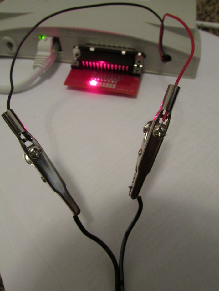
If everything works the fun begins. A printf "\xFF" | nc 192.168.1.170 9100 should turn on all the leds.
A sample program was constructed in C# to simulate the Knight Rider dash or a Cylon.
This guide will walk through how to install network caller ID (NCID) on a headless raspberry pi. The primary goal of this is to create a blacklist to prevent unwanted spam telephone calls.
Hardware needed:
Raspberry Pi, a model b was used but any should work
SD Card, any larger than 4gb should work
5V power supply. The modem appears to take a large amount of current. The first 1 amp power supply was unstable so it was replaced with a 2 amp version
Modem, a Zoom 56K USB Modem Model 3095 was used. This was sourced from Ebay.
Un-tar the archive using tar -zxvf ncid-X.XX.X-src.tar.gz (replace the X.XX.X with version number)
Run sudo-apt get update then grab a copy of sudo apt-get install libpcap0.8*
Navigate to the folder with the build scripts and run sudo make ubuntu-install
Open the config file with sudo nano /etc/ncid/ncidd.conf
Make the following changes to the configuration file: set ignore1 = 1
set hangup = 1
set ttyport = /dev/ttyACM0
set lockfile = /var/lock/LCK..ttyACM0# Make sure your modem is located here
open nano /etc/ncid/ncidd.alias
Comment out this line with a “#” #alias LINE - = POTS
Make the NCID daemon automatically start up sudo update-rc.d ncidd defaults
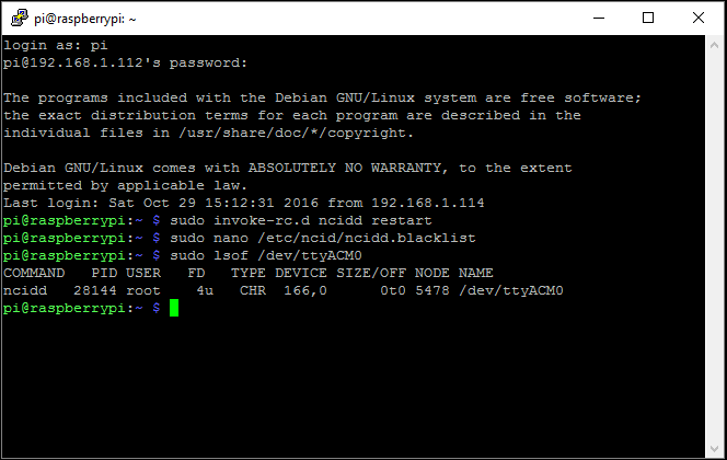
The blacklist is located here and should be edited /etc/ncid/ncidd.blacklist
Finally run sudo invoke-rc.d ncidd restart to get the service running. This also appears to need to be run after editing the blacklist.
Notes:
If the services is not working these links were useful during troubleshooting: