This post will cover building a low power solar WIFI sensor node using a Wemos D1 module. The module is loaded with ESPEasy firmware and reports sensor data to a Domoticz server.
The sensor nodes can be used with any of the sensors the ESPEasy firmware can support. This includes temperature, moisture and a host of other physical and environmental inputs and outputs. A full list is located here: https://www.letscontrolit.com/wiki/index.php/Devices
Hardware:
Bill of materials:
| Description | Notes | Qty |
|---|---|---|
| JST-XH 2 Pin Header Male | 2 | |
| JST-XH 2 Pin Pigtail Female | 3 | |
| 1N4004 Diode | 1 | |
| .1″ Header Female (8 Pin) | 2 | |
| .1″ Header Male (8 Pin) | 2 | |
| .1″ Header Male (2 Pin) | For Sleep | 1 |
| .1″ Header Male to Female (8 Pin) | 2 | |
| TP4056 DW01A Charger Board Module | 1 | |
| Mini 12-cell Polycrystalline Solar Panel 6V | 1 | |
| 18650 or other lithium ion Battery | 1 | |
| Wemos D1 | 1 | |
| Wemos D1 Mini LiPo Battery Shield | 1 | |
| Heatshrink for battery wires | 1 | |
| Dry Box | 135*80mm*40mm | 1 |
| Optional PCB | Gerber Link Below | 1 |
| Optional Target Sensor | 1 |
The first two versions of this sensor node were built by hooking .1″ headers together and fixing all the components inside a large dry box with double stick tape. Here is a photo of the first two versions:


These versions were somewhat time consuming to reproduce so a PCB was spun to help speed up build times.
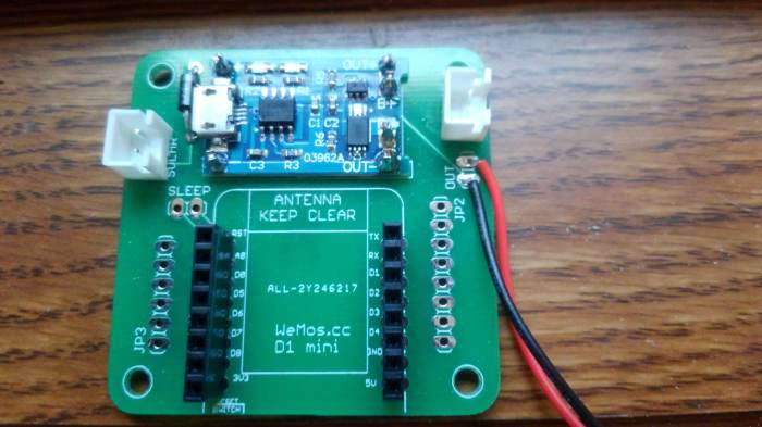
Here is a link to the gerbers: https://github.com/mdunakin/PCB/tree/master/WemosD1Plate
This PCB takes power in from a solar cell on the left JST-XH connector. This is fed through a 1N400X diode that is acting as a bypass diode. This then feeds into the Blue PCB shown at the top. This PCB acts as a charge controller. Ideally the charge controller on the Wemos D1 mini LiPo battery shield could be used but it lacks over discharge protection. This is the reason for the secondary charge controller. The left JST-XH connector is used to attach the LIPO battery and the red and black wire are fitted with a female JST-XH connector that plugs into and powers the Wemos D1 mini LiPo battery shield.
JP2 and JP3 are used to break out the IO pins on the Wemos D1 mini. The sleep jumper allows for the Wemos D1 to be put into a deep sleep mode conserving battery power. The sleep function is documented here: here: https://www.letscontrolit.com/wiki/index.php/Devices
Configuration:
Before getting sensor readings you will need to get a copy of Domoticz from here: https://domoticz.com/ I recommend running this on a computer that will be on all the time and also running it as a Windows service.
You will also need to flash your Wemos D1 with the ESPEasy firmware https://www.letscontrolit.com/wiki/index.php/ESPEasy This was a simple process. You just grab the installer from the link above. Run the executable and point it at the correct serial port.
Hardware Configuration:
The hardware configuration can be broken down into two main parts. Configuring the ESP8266 to send the data and configuring the Domoticz server to receive the data.
Before configuring the sensor it needs to be created in Domoticz to get the IDX number so the ESP8266 knows where to send the data.
This is done by adding “dummy” hardware in Domoticz and then selecting the “create virtual sensors” button.

After that create a “Temp+Hum” sensor:

Here is the configuration for the ESP8266 using ESPEasy firmware:

Make sure that the Domoticz server is configured on the ESP8266:

Battery Monitor:
Battery voltage monitoring is described here:
Here is a setup screen on ESPEasy:

Here is the corresponding Domoticz setup:
Create a dummy Hardware device:

Click the create virtual sensors button
Add a voltage sensor

Sleep:
To get ESPEasy to sleep, configure each configured device to take readings at the interval you desire on the devices tab. Then under the config tab set the interval.
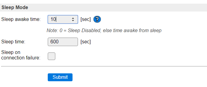
After that cut power by disconnecting the battery and solar cell and set the sleep jumper on the PCB and re-power up the system. If everything is configured correctly the device will now sleep between readings. Note, when first powered up the ESP8266 will have a responsive web server for 30 seconds before going to sleep.
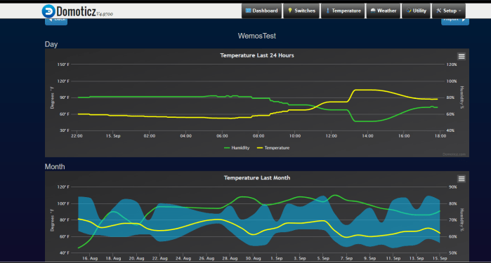
Here is some data that was collected from a previous sensor deployed during summer:

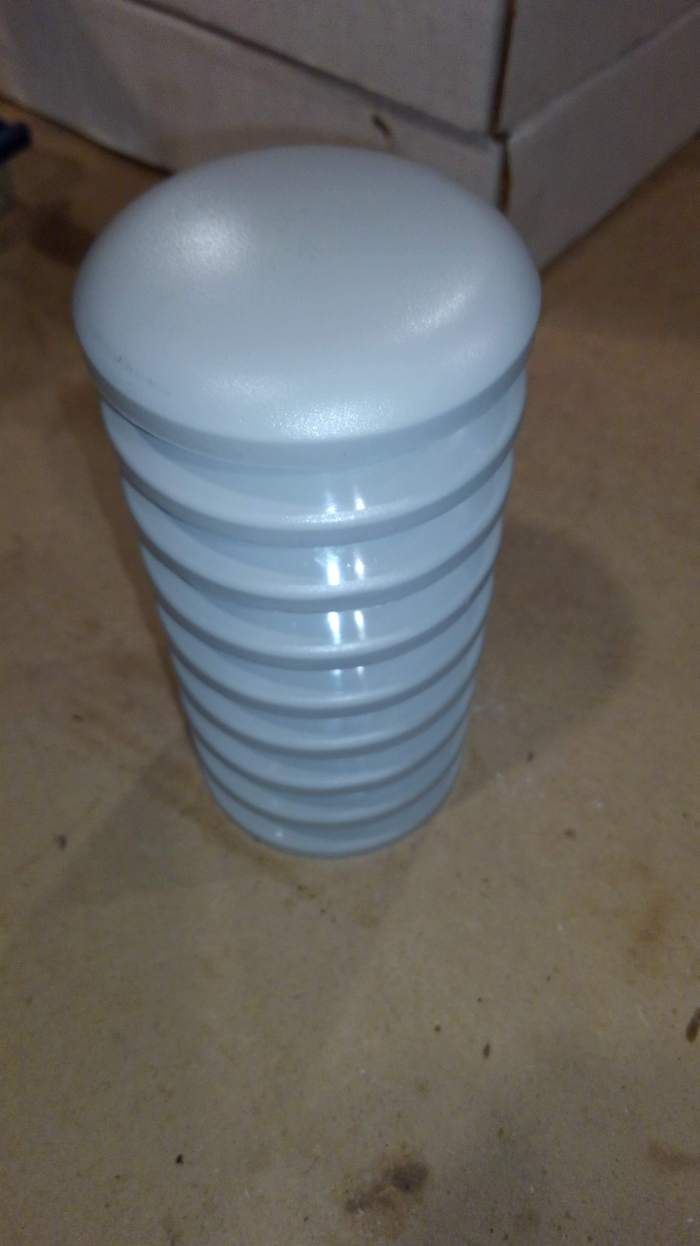
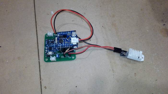
The PCB assembly and battery are packaged in a small dry box with a solar cell mounted to the lid. The DHT 22 will be placed into a Stevenson Screen that was purchased from: http://www.misolie.net/plastic-outer-shield-for-thermo-hygro-sensor-spare-part-for-weather-station-transmitter-thermo-hygro-sensor-p-515.html