Wireless RS-232 with ESP-Link and an ESP8266

This will show how to create a wireless WIFI serial port. This is accomplished by flashing esp-link onto an ESP8266 and using a  level shifter to convert 3.3V signals on the ESP8266 to computer levels.

Parts Needed:

  • nodemcu amica R2
  • RS-232 Level shifter using a MAX3232 Available from ebay by searching “MAX3232 converter” make sure you get one with four pins like this photo:

s-l400

  • PCB Order from OSH Park
  • Micro USB cable
  • Micro USB 5V power supply for ESP8266
  • Windows PC
  • Optional RS-232 Loopback
  • Optional RS-232 DB9 gender changer


Flashing the nodemcu amica:

  1. Get the latest esp-link firmware from https://github.com/jeelabs/esp-link/releases
  2. Download the Nodemcu flashing software at https://github.com/nodemcu/nodemcu-flasher/archive/master.zip
  3. Connect the nodemcu amica to the computer using a USB Cable
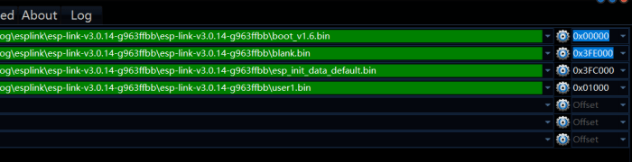
  4. Setup the Nodemcu flashing software to flash the correct firmware files at the correct memory addresses See https://github.com/jeelabs/esp-link/blob/master/FLASHING.md for details: Flash
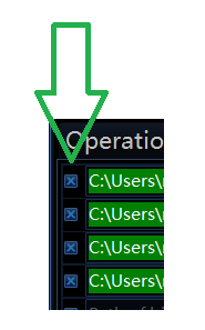
  5. Make sure that the checkbox is checked for all the files. It appears to not flash the file if it is unchecked:

buttons

Now you should be able to hit the flash button:

flash2

Setting up the esp-link software:

  • On a computer look for an open wifi hotspot with a name like  ESP_[??????] and connect to it.
  • In a web browser navigate to http://192.168.4.1/
  • On the right hand side of the website click on the Wifi Soft-AP and configure your SSID and add a password if you want. Note you will have to re-connect to the device if you change the SSID or password.
  • On the home tab configure the GPIO using the presets drop down choose the ESP-12 swapped option:

ESP12Swapped

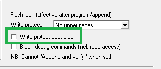
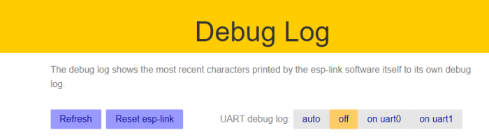
  • On the debug log tab turn off debugging since it will echo on the serial port:

debugoff

Hardware

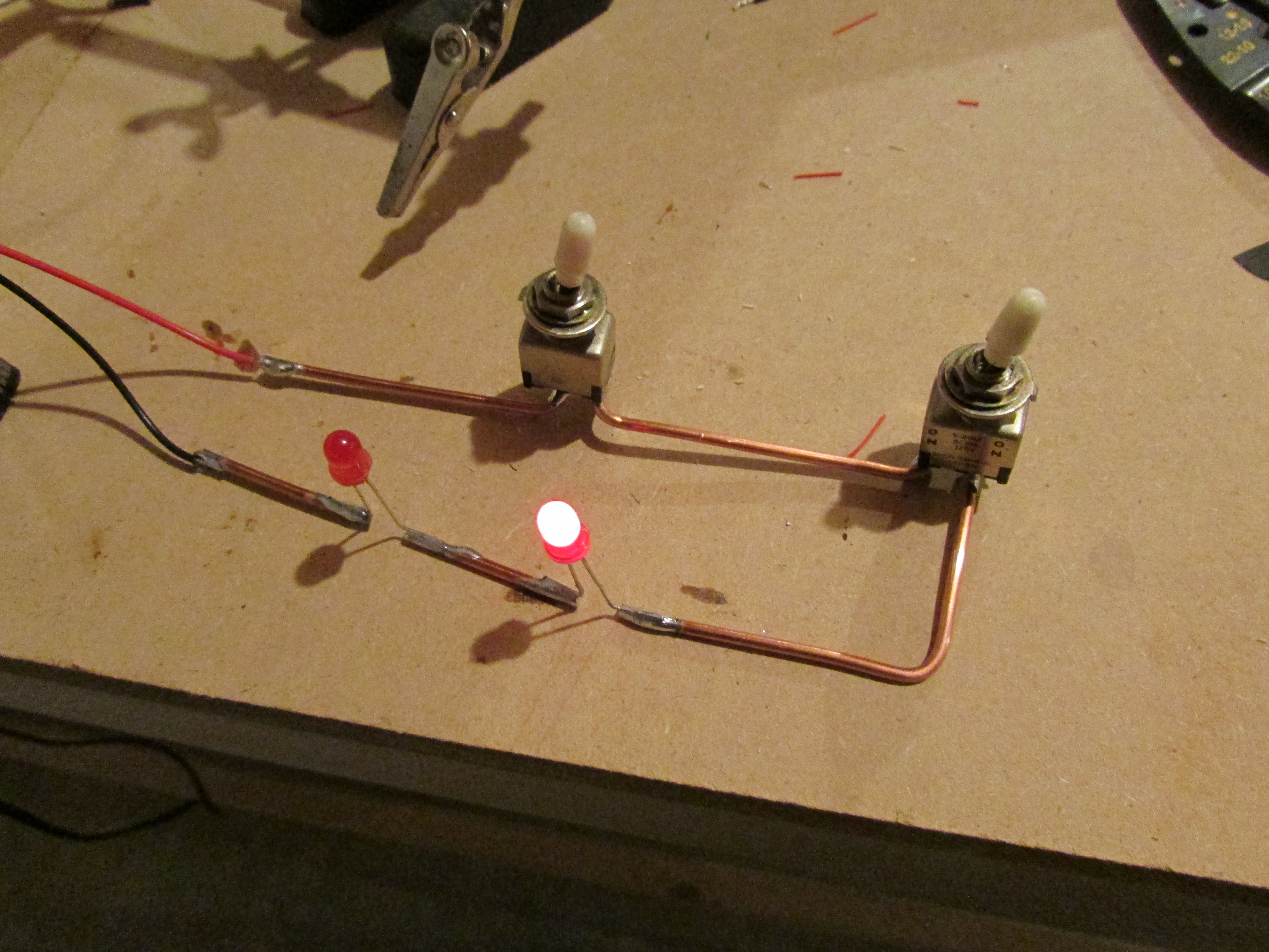
The PCB connecting the ESP8266 and the level shiftier will need to be soldered as shown in this photo:

IMG_5776

If you are unsure of the orientation make sure that the VCC and Grounds of the ESP8266 module are connected to the respective VCC and GND pins on the level shifter.

Testing and Use

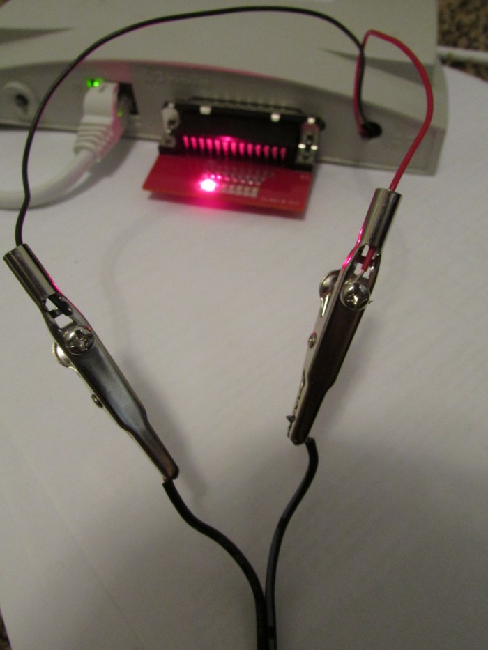
The esp-link software has a built in serial terminal that works OK for a quick test. It is located on the uC Console tab. A quick way to test if everything is working is to use a loopback. The loopback can be as simple as connecting pins 2 and 3 of the dsub on the level shifter together. When the loopback is attached anything typed should be echoed in the console. When it is disconnected no echoing should occur.

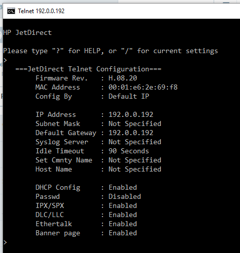
The serial port can also be accessed using telnet. This can be done using a telnet client like PUTTY http://www.putty.org/

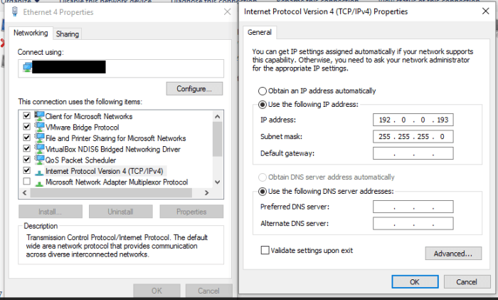
Connect to the device 192.168.4.1 on port 23 using telnet

Network Attached GPIO with HP Jetdirect

The goal of this is to create some network attached GPIO with some of the HP Jetdirects in my junk box. Here are some of the web sites used to figure this out:

As far as hardware the project was started with a Jetdirect 300x this was replaced with a 170x. The 300x has 10/100 base t which is why it was initially chosen. This was later replaced with the 170x which is only 10 base t. If you are looking to buy hardware, shoot for the 170x. The 300x, at least the one tested, does not appear to be as stable as the 170x.

The Jetdirects did not come with a power supply. The power connector was a somewhat weird diameter. Sourcing the power supply on Ebay proved more time consuming and expensive than desired. The search did lead to this listing which is hilarious.  Just picture a person driving with a wired network and a printer in their car. No one probably ever buys this…

carcharger

The easiest solution for this was to pop open the case and solder some wires to the power connectors. That was also a problem since HP was nice enough to use some super tiny Torx security bits. A quick trip to the hardware store and the screws were no match for my new set of security screwdriver bits.

These wires were then attached to a surplus 12v wall wart.

img_5602

For testing a PCB was created and the design was sent to https://macrofab.com/.

schematicdb25

The original PCB did not have the connection on the DB25 connector between pins 1,  10, 13 and 15. This was added later on with some red 30 awg wire wrap wire.

The first problem that was encountered was finding the Jetdirect’s IP address. Usually this would be a simple task. All that would be required is holding down a button on startup and the jet direct would print out a configuration page that lists its IP address. This would be easy other than the fact that I no longer own a printer with a parallel port interface. The device is supposed to have a default IP of 192.0.0.192 so that was tried first. After some reading it appears that if the device is power cycled while holding the
“test”button and releasing after 5 seconds it will go into reset and have factory defaults. After this was accomplished it was possible to ping, telnet and connect to the device using a web browser.

adapter

The telnet interface looked somewhat primitive so I opted for the web interface. The web interface failed to load in chrome so IE was tried. IE gave this lovely error:

error

After updating Java and adding the IP to the trusted sites in the java control panel, the web interface still did not work.

javaerror

After some reading this is due to stricter security in the newer versions of Java. The work around for this was to use the telnet interface.

telnet

The jet direct’s default IP address of 192.0.0.192 was not convenient so it was changed to be in the 192.168.1.xxx range. This was done by issuing the command ip: 192.168.1.170 (or whatever IP you want) hitting enter then typing quit. After that wait one minute and power cycle the Jetdirect. The Jetdirect should now show up hopefully at the new IP. One other setting also needs to be set to gain control of the Jetdirect’s parallel port. The “set cmnty name” setting also needs to be set. This can be done by sending set-cmnty-name: private then typing quit.

One more thing needs to be done to trick the Jetdirect into thinking it has a printer attached. This is setting the npPortCentronicsHandshaking value in the jet direct. This was done with SNMPGetSet available here: http://www.fileguru.com/SNMPGetSet/download. The register is set by putting the value of 1.3.6.1.4.1.11.2.4.3.13.4.0 into the OID box at the bottom of the form. Once that is done hit the SNMPGet button. The returned value should be 3.

setoid

To set the value change the value in the box to 2. After changing the value of 2 make sure that you set the value type to ANS1_INT. Then press the SNMPSet Button.  If you do not change the value type the setting will not save.  You can confirm the setting was saved by pressing the SNMPGet button again.

setoid2

If everything is working correctly the Jetdirect should now be able to be controlled. To verify everything is working correctly first check to see if the Jetdirect will open port 9100. This can be done from a Unix shell with netcat. Command nc -vz 192.168.1.170 9100 you should see  [tcp/*] succeeded! if everything is working. If that does not work try port 23. If you can connect on port 23 but not on 9100 the Jetdirect does not think a printer is connected. Check your wiring especially on pins 1,  10, 13 and 15.

If everything works the fun begins. A printf "\xFF" | nc 192.168.1.170 9100 should turn on all the leds.

A sample program was constructed in C# to simulate the Knight Rider dash or a Cylon.

Here is the code: https://github.com/mdunakin/JetDirectDemo

Here is a video of the code running:

Rfcat on eZ430-Chronos Dongle with CC-Debug

Steps to get Rfcat working on a eZ430-Chronos Dongle.

If you are interested on what Rfcat is watch this video https://youtu.be/ZWx8y5_J0Xo

Acquiring supplies

You will need 1 eZ430-Chronos kit (more specifically the PCB shown in the green box below)

EZ430-Chronos

Note: this will only work on older eZ430-Chronos dongles with the black PCB. The newer kits have a white PCB that contains a CC1101. To the best of my knowledge the Rfcat project only runs on the CC1111. The eZ430-Chronos kit used was purchased from TI on 08/2011 during a sale for $24.50 USD.

You will also need 1 CC-Debugger. They can be acquired from TI or in my case Ebay. Buying development tools from Ebay can be a gamble but the price was just too good for this CC-Debugger.

debugger

And here is the dongle and CC-Debugger:

IMG_4524


Wiring:

Wiring the dongle is fairly straight forward. Since a bootloader will be installed it only really has to remain wired for a short period of time and does not need to be robust at all. Due to this some 30 awg solid core was used.

IMG_4528

A diagram of how to wire the part can be found on page 47 of this pdf http://www.ti.com/lit/ug/slau292g/slau292g.pdf.

WireDiagram

Note: the connector is wired as it would be looking into the CC-Debugger. If you are unsure of the connector orientation find a CC debugger pin-out and look at pins 1 and 9 (vcc and gnd) with a DMM.

Updating the CC Debugger

The easiest way to update the CC-Debugger to the latest firmware appears to be getting a copy of Smart RF Studio http://www.ti.com/tool/smartrftm-studio. Run the software with the CC-Debugger connected and you will be able to flash the CC-Debugger with the latest firmware.

Flashing the Chronos Dongle

Flashing the chronos dongle was done with SmartRF Flash Programmer (Version 1) http://www.ti.com/tool/flash-programmer. Version 2 was avoided since it did not have an apparent way to write protect the bootloader.

The hex files for Rfcat can be found here: https://bitbucket.org/atlas0fd00m/rfcat/downloads

The bootloader (RfCatChronosCCBootloader-150225.hex) was written first:

Flashing

Then the actual code was written (RfCatChronos-150225.hex) Make sure that the Write protect boot block check box is checked for this step.

bootBlock

If you have done everything correctly you now should have an Rfcat dongle.

Using the Rfcat dongle

An old netbook was used to test the dongle. It was re-formatted and 32 bit Ubuntu 14.04.4 LTS was loaded on to it http://releases.ubuntu.com/14.04/.

After setting up the OS python-usb and libusb were acquired.

After that the rfcat tarball was unziped and  sudo python setup.py install was run to install rfcat.

A udev rule was added for the dongle but it ended up not working so it will not be documented. The tool can be run without the udev rule by issuing sudo rfcat -r

Screenshot from 2016-04-10 18_09_27

success!!

Wall Mounting TV

This is a post discussing wall mounting my TV. Here is the before photo:

tvBefore

Behind the left speaker is a computer that is connected to the TV. The white cabinet is hiding a router and cable modem. The house was wired with a cat 5 and coax run near the TV. After some searching an adapter was found that allows for HDMI to be run over CAT-5 (J-Tech Digital JTDHDEX-1 HDMI over single CAT 5E,6,7). With some re-wiring the Modem, computer and router were able to be relocated to the basement. The TV was mounted using a Cheetah Mounts APTMM2B TV Wall Mount. The computer was using a Logitech Keyboard K400 keyboard. This worked fine with the computer close to the TV. Once the computer was moved to the basement the keyboard was not as responsive as hoped. This was fixed by using a 50 foot active USB extender to move the USB adapter closer to the TV. Overall the install turned out clean with no visible cables:

IMG_4462


Sanyo PLC-100N Led conversion

While browsing the local E-waste recycler I came across this a Sayno PLC-100N projector with what appeared to be a burned out bulb. The projector was on sale so I figured it was worth a shot on getting it up and running.

IMG_4061 IMG_4037

After taking the projector home and powering it up the projector emitted a strong electrical burning smell with the bulb connected. After a quick search the cheapest  replacement bulb for this projector was around $100. This seemed steep for something that may or may not work. My initial thought was to use a large 100 watt LED that I have experimented with in the past. This would be significantly cheaper than the replacement bulb and hopefully have a longer life span and run cooler.

After some initial diagnosis, with the bulb removed, the projector would briefly power up then shut down. My initial guess was the projector was sensing the lack of a bulb. After examining the bulb power supply it had three pairs or wire going to/from it. The black and white wire were power and the white wires connected to the bulb. The pair of pink wires went to an optocoupler in the supply for isolation. After some careful probing it was determined that disconnecting the pink wire harness from the main board tricked the projector into thinking the bulb was OK. Since the bulb power supply was no longer needed the black and white power leads were disconnected to permanently power the bulb supply off. The supply could be physically removed but it is used as a mounting point to secure the outer case so it was left in tact.

IMG_4030IMG_4034

Now that the projector was working it was time to modify it to accept a new LED based bulb. After some light metal work the LED and a heat sink were attached to the bulb bracket. This allows the LED to be removed if I need to service it in the future. The old bulb is shown on the right and the new LED bulb is shown on the left.

IMG_4057

Here is a shot of the bulb installed in the projector.

IMG_4056

The bulb is powered by a HP power brick most likely from a printer also from the E-Waste recycler. The Brick sources enough current to make the projector visible while keeping the LED well below its rated max current. Low current and the heat sink keeps the LED cool while running the projector for long periods of time. A good Future improvement for this project would be to shoehorn the power brick into the projector case. This could be accomplished by removing the old lamp driver PCB and putting the power adapter in its place.  Taking a shot of the projector working proved difficult so it was omitted from this post. Overall this was a simple project with a usable result. The projector currently has a Raspberry Pi running OSMC  to it.

IMG_4062

Impossible Circuit

This YouTube video created by Henryk Gasperowicz interested me so I decided to make a replica of the circuit shown in the video.

The circuit appears to be a simple series parallel circuit but behaves differently. The trick is a small oscillator enclosed in the 9V battery snap. This oscillator turns the DC from the battery into a square wave. Hidden diodes on the switches and LEDs steer the LEDs  in the circuit. A schematic for this circuit can be found on Henryk Gasperowicz Google+ page. He builds all his circuits dead bug style. Dead bug style circuits are small but also difficult to build. Due to this a PCB was designed for this circuit.

thumb_i

Due to the small size OSH Park charged $1.10 shipped. The 0402 parts were hand soldred without a microscope so it may look a little rough. Here is a shot of the assembled board and the circuit in action

IMG_4022IMG_4024